A constant-current trickle charger could be implemented by connecting a simple constant-current source to a battery, but a current that is appropriate for maintaining a NiMH battery at full charge is insufficient to charge a discharged battery in a reasonable period of time. If the constant current is increased to shorten the time, it will be too much current to force through a fully-charged battery, causing damage. Digital smart chargers exist for NiMH batteries. One such design steps the charging current down as the charge builds up, before shutting off or leaving the battery on a low trickle charge to maintain it in a state of full charge. The design I present here does essentially that, but tapers the charging current down instead of stepping it down. It is a simple design, utilizing a few analog components. It is practical in the case where there is no rush to get the battery charged. This circuit can get it done in 24 hours, while putting no stress on the battery.
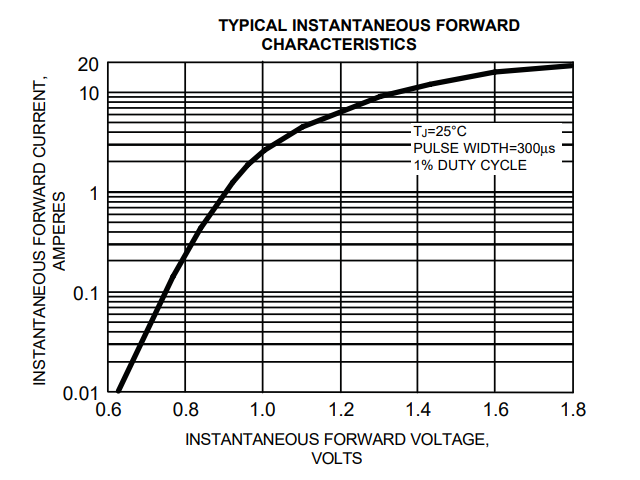
During charging, a NiMH cell acts like a nonlinear resistor. Discharged, it presents low resistance to charging current at a given applied voltage, and that current tapers down as the state of charge increases. For example, a AAA NiMH cell exhibits an effective resistance of about 12 ohms at full discharge, to about 120 ohms at full charge. However, a constant voltage cannot be applied to a NiMH cell for charging; it must be allowed to vary with the state of charge. Having a logarithmic V/I curve, a diode acts as a nonlinear resistor, as seen in the graph below. The nonlinear aspects of a diode and a NiMH cell are complementary, such that a diode can be used to taper down the current in response to rising terminal voltage as the cell charges.
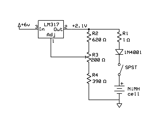
As seen in the schematic diagram, the LM317 voltage regulator provides a constant 2.1 volts to the load consisting of a 1 ohm resistor, a rectifier diode, and the NiMH cell being charged, in series. The voltage across the battery rises as it charges, reducing the voltage across the diode, causing its effective resistance to increase as an inverse logarithmic function of the voltage across it, reducing the current. Resistor R1 is there to provide a way to monitor charging current by measuring the voltage across it. In the case of a 1 ohm resistor, the voltage across it in millivolts correlates 1:1 to the current through it in milliamperes.
Potentiometer R3 is used to set the output voltage of the regulator to the value required to satisfy charging requirements. It should be set to 2.1 volts before setup with a battery begins. Two parameters of importance are the initial charging current of a fully-discharged cell, and the trickle charging current of a fully-charged cell. Probably the more important of the two is the trickle charging current, especially if charging is not stopped after full charge is attained. For a NiMH cell of 1000 mAh capacity, the trickle charging current at full charge should not be more than 0.02 times capacity, in this case 20 mA. Therefore, R3 should be adjusted for that value of current, or less, through a fully-charged cell. At that setting, current through a fully-discharged cell is about 120 mA, or 0.12 times capacity, and the time to charge a fully-discharged cell is about 24 hours.
Monitoring the current provides insight to the charging process. To do that, I connected an analog VOM, set to full-scale deflection at 0.1 volts, corresponding to 100 mA of charging current, across R1. What I observed is that charging current tapered down slowly at first, then more slowly with the passage of time, eventually approaching the final trickle charging current asymptotically. That is, approaching it ever more slowly until arriving at a final value that does not change perceptibly over a few hours. At that time, the cell is fully charged, and it can be left charging at that trickle rate, or the charging current can be switched off by means of the SPST switch.
For a low-self-discharge cell, such as the EBL NiMH AAA cell, advertised to maintain 80% of its charge after three years, I am inclined to switch the charging off a few hours after the final charging current is reached. The reason for that is, to lose 200 mAh of charge over a span of three years, the average discharge rate is only 7.6 microamperes. At that rate of self discharge, 15 mA of trickle current would be more than a thousand times the current necessary to counteract self discharge. It would be practical to set the trickle current to 12 microamperes only if is necessary to maintain the cell at full charge indefinitely; that is, for years. I think it is better, for the battery, to switch charging current off than to keep it on 15 mA of trickle current indefinitely. Typically, the cell will be put into use within days of being charged, during which the amount of self-discharge is negligible.
If the charger is to be set up with a cell that is fully discharged, R3 should be adjusted to set the charging current at about 0.1 times the capacity of the battery. The final setting of R3 can be done to adjust the trickle charging current when the cell is fully charged. R3 should be adjusted again if a new type or brand of cell is to be charged. For an AA battery having 2100 mAh capacity, initial charging current for a fully discharged cell was found to be 250 mA, and final trickle charging current should be 40 mA or less. At those higher currents, the voltage drop across the diode will be greater, possibly necessitating slightly higher voltage output from the regulator IC.
Copyright 2025 Steven A. Brown